Dodge Seat Wiring

powderhoundbrr

Active VIP Member
Joined
Apr 24, 2008
Messages
529
Reaction score
1,018
Location
Kimberley, BC
OK so the switch on my 06 Power Wagon that moves the drivers seat back is toast. Every other switch works but I can't move the seat back right now. My five year old just moved the seat to the very front so I can barely get in the truck right now and driving is me with my knees pressed up against the steering wheel. My wife gets a good laugh out of it.

Anyway I leaving on a road trip tomorrow and I need that seat back. I live in a small town and can't get a switch in time.

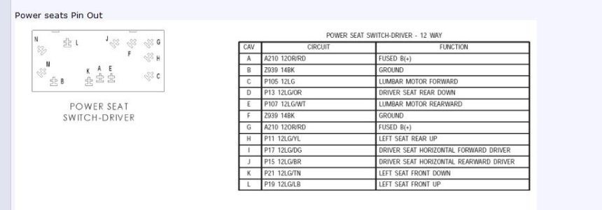
Sooooo I took the switch off and see the pins in the diagram below. Is there a way I can energize (J) which is driver seat rearward so I can get the seat to move back. I tried using wire and jumping a few different circuits but didn't have any luck. I am hoping someone here might be able to give me instructions on what pin holes to connect together to make it work. If not I have a very uncomfortable 10 hour drive ahead of me tomorrow.
 

Attachments

  • Wiring.JPG
    Wiring.JPG
    48.4 KB · Views: 55

JaySimon

Active VIP Member
Joined
Mar 13, 2009
Messages
2,396
Reaction score
2,102
Location
Kimberley BC
Cranbrook dodge doesn't have a switch?

If they do, and you can't get to town, I can bring it back to Kimbo for ya after work, send a PM if that's the route you want to take.
 

Summitric

SUPER COOL MOD & Supporting Vendor
Moderator
Joined
Oct 21, 2006
Messages
48,007
Reaction score
32,148
Location
Edmonton/Sherwood Park
Website
www.bumpertobumper.ca
On the wiring connector test cavity j for power...... If none, then jump cavity j to cavity a for a split second and see if the seat moves........... If it does, then connect until seat is all the way back :)...... If it doesn't move, might be a burned out power seat motor or linkage problem :(
 

TylerG

Super Mod Geek
Administrator
Moderator
Joined
Nov 7, 2006
Messages
30,487
Reaction score
27,733
Location
Parkland County
On the wiring connector test cavity j for power...... If none, then jump cavity j to cavity a for a split second and see if the seat moves........... If it does, then connect until seat is all the way back :)...... If it doesn't move, might be a burned out power seat motor or linkage problem :(

if no power, could also be blown fuse, no?
 

Summitric

SUPER COOL MOD & Supporting Vendor
Moderator
Joined
Oct 21, 2006
Messages
48,007
Reaction score
32,148
Location
Edmonton/Sherwood Park
Website
www.bumpertobumper.ca
Before any testing of the power seat system is attempted, the battery should be fully-charged and all wire harness connections and pins checked to ensure proper continuity and grounds. Also ensure that the seat being diagnosed is not jammed by foreign material. With the dome lamp on, apply the in the direction of the concern. If the dome lamp dims, the seat may be jamming. Check under and behind the seat for binding or obstructions. If the dome lamp does not dim, proceed with testing of the individual components and circuits.

For complete circuit diagrams, refer to the appropriate wiring information. The wiring information includes wiring diagrams, proper wire and connector repair procedures, details of wire harness routing and retention, connector pin-out information and location views for the various wire harness connectors, splices and grounds.

Operate the and move the seat in all directions. The seat should move in each of the selected directions.

If the power seat adjuster fails to operate in more than one direction, proceed as follows:


  1. Inspect the power seat adjuster motors to ensure the electrical connectors are fully seated to the motors. If OK, go to Step 2. If not OK, connect the electrical connector to the fully seated position.
  2. Check the power seat fuse in the integrated power module. If OK, go to Step 3. If not OK, repair the circuit as necessary and replace the inoperative fuse.
  3. Remove the from the side panel. Check for battery voltage at the fused B(+) circuit cavity of the power seat switch wire harness connector. If OK, go to Step 4. If not OK, repair the open circuit to the integrated power module as required.
  4. Check for continuity between the ground circuit cavity of the wire harness connector and a good ground. There should be continuity. If OK, go to Step 5. If not OK, repair the open circuit to ground as required.
  5. If the switch tests OK, check the wire harness between the and the motor. If the circuits check OK, replace the inoperative power seat adjuster assembly. If the circuits are not OK, repair the wire harness as required.
 
Top Bottom